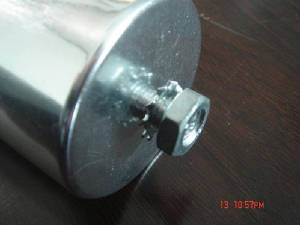
Fixing
The threaded bottom stud has to be fastened with certain torques:
M16 bottom stud for diameters <53 mm: torque 10 Nm
M12 bottom stud for diameters 53 mm: torque 4 Nm
Grounding
The M16 bottom stud is used for grounding.
Connect it to the ground by cable, or connect the capacitor to any other condutive item which is connected to the ground.
NOTE: Suitable connectors have to penetrate existing layers to lacquer to ensure good, constant conductivity and
sufficient current carrying capabilities.
If grounding is done via the metal chassis the capacitor is mounted to, then the layer of varnish beneath the washer
and nut should be removed.
Connecting
When connecting, avoid bending cable lugs or cable lugs or cables, orthe use of other forms of mechanical force on the
terminals. Otherwise, leakage could disable the safety device!
Ensure firm fixing of terminals, fixing torque to be applied as per individual specifications.
In any case, the maximum specified terminal current may not be exceeded.
Parallel connections of capacitors via the SIGUT terminal is not recommended.
Connecting the Supply Cable
Cable specifications: The connection cable must be of flexible type, material should preferably be copper.
NOTE: Do not use solid core cables!
Maximum cable cross section is for 16mm squared.
The connection cables to the capacitor should be dimensioned for a current of at least 1.5 times the rated current so
that no heat is conducted into the capacitor.
Maximum Terminal Currents
Do not exceed the maximum allowable current
Attaching the Supply Cable
Attach the supply cable only with the maximum permissible torque values or 1.2 Nm
Using Discharge Resistors
Discharge resistors are included in the delivery package, premounted by the factory.
They are required for discharging of capacitors in order to protect operating personal (risk of electric shock hazard)
and for re-swtching capacitors in automatic PFC equipment phase opposition!).
Discharge resistors are designed to discharge capacitors within 180 seconds down to 75 volts or less.
Make sure that the correct resistor is used to replacement e.g. Ohm-value and push-on connector diameter.
Discharge the Capacitor
Before re-switching, capacitors have to be discharged to 10% of the rated voltage or even lower.
A discharge resistor can be easily replaced by pressing it on the exposed top on the SIGUT terminal.
Caution! Discharge and short circuit the capacitor before handling!
Inrush Current Limitation
Switching LV PFC capacitors can cause high inrush currents of more than 200 times the rated current, especially when
they are connected in parallel to others that are already energized. This may cause additional stress to contactors
as well as to capacitors and reduce their life cycle.
Inrush currents have a negative effect on power quality, e.g. transients, voltage drop. Although MKK AC design
with its wave cut has high impulse handling capability, inrush current limitation is required e.g. contactors with pre-charging
resistors for pre-loading of capacitors.
or
serial air coils (approx. 8 turns in the connection cables between contactor and capacitor with a diameter of 10 cm)
IEC 831 Standard and Reference
According to IEC 831 standard, a maximum of 5000 switching operations per year is acceptable. Before considering
higher number of switching operations, please contact our service.
Harmonics
Harmonics are sinusoidal voltages and currents with frequencies that are multiples of a 50 Hz or 60 Hz power supply frequency.
Harmonics result from the operation of electrical loads with non-linear voltage-current characteristics.
They are mainly caused by loads operated with modern electronic devices, such as converters, electrical drives, welding
machines and uninterruptible power supplies (UPS).
Attention! In applications with harmonic distortion only power capacitors with reactors, namely de-tuned capacitor
banks, should be used. Depending on the chosen series resonance frequency, a part of the harmonic current will be absorbed
by the power capacitor. The rest of the harmonic current will flow into the grid. The use of power capacitors
with reactors reduces harmonic distortion and minimizes the disturbing effects on operation of other loads.
Avoid Reasonance Conditions
The most important reason for installing de-tuned capacitor banks is to avoid resonance conditions. Resonance conditions
may multiply existing harmonics and create power quality problems as well as damages to distribution equipment.
Occurrences of resonance should by all means be avoided by appropriate application design!
Overpressure Disconnector
Electrical components do not have unlimited life expectancy; this also applies to self-healing capacitors.
All of our capacitors are consequently fitted with a disconnector that responds to overpressure. If numerous electric
breakdowns occur at the end of life or as the result of thermal or electric overload (within IEC 831 specification), the formation
of gas produces a rise in pressure inside the capacitor case.
This causes a change in length because of curvature of the lid or stretching of the expansion bead. Expansion beyond
a certain degree will separate the internal wires (tear-off fuses) and disconnect the capacitor from the line.
Caution! To ensure full functionality of an overpressure disconnector, the following is required:
1.) The elastic metal top must not be impaired:
connecting lines must be flexible leads (cables), there must be sufficient
space for expansion above the connections (stated for the difference models),
folding groove must not be retained by clamps.
2.) Maximum allowed fault current of 10000 A in accordance with UL 810
standard must not be exceeded.
3.) Stress parameters of the capacitor must be within the IEC 831 specification.
Over Current/Short Circuit Protection
HRC fuses or MCCB for short circuit protection have to be used.
Short circuit protection equipment and connection cable should be selected so that the 1.5 times rated current of the
capacitor can be managed permanently.
HRC fuses do not protect the capacitor against overload, it is only a short circuit protection!
HRC fuse rating has to be 1.6....1.8 times nominal capacitor current.
Do not use HRC fuses for switching capacitors (lightning arc!).
Use thermal/magnetic overcurrent relays for overload protection.
Maintenance
Caution! Disregarding the following measures may result in severe operation failures, bursting and fire.
Check tightness of the connections/terminals periodically.
Clean the terminals/bushings periodically to avoid short circuits due dust or other contamination.
Check the short circuit protection fuses.
Take current reading twice a year and compare with nminal current. Use a harmonic analyser or true effective RMS-meter.
In case of a current above the nominal current check your application for modifications.
If a significant increase in the amount of non-linear loads has been detected, then a consultant has to be called in
for a harmonic study.
In case of the presence of harmonics installation of a de-tuned capacitor bank (reactors) must be considered.
Check the discharge resistor/reactors and in case of doubt check their function:
(1) Power the capacitor up and down.
(2) After 180 seconds the voltage between the terminals must decline to less than 75 volts.
Check the temperature of energized capacitors. In case of excessive temperature of individual capacitors, it is
recommended to replace this capacitor, as this could be an indication for loss factor increase which is a sign for reaching
end of life.